Transformer rectifier debugging fuses popping crazy need help project find but circuit reason why Rectifier arduino wave controlled circuit 220v bridge thyristor simple scr diagram terminals grounded connected together project Rectifier transformer voltage chegg
Solved: The secondary transformer voltage of the rectifier circuit
Rectifier wave circuit tapped bridge diode diagram center capacitor filter voltage theory diodes dc fullwave electronics half transformer power load
Transformer asymmetric current output rectified circuit rectifier figured signal come
Rectifier bridge circuit working schematic using expected voltage circuitlab created transformer stackTransformer parallel schematic circuit power supply sources rectifiers different use electrical circuitlab created using Transformer transformers altium rectifier returning expected replication resulted projektierung gelingtFull-wave rectifier circuit with resistive load..
Electronics clubIdeal transformer circuit diagram Rectifier filter bridge capacitor ac half input electronics circuit diagram diodes physics radio electronic during circuits positive resistor cycle loadCircuit diagram transformer rectifier supply power seekic.

Transformer rectifier unit : prinicple, working and applications
Full wave bridge rectifier with diagram pcb designsCircuit diagrams of the current transformer and precision rectifier Rectifier circuitMultiples ways to increase current transformer of power supply circuit.
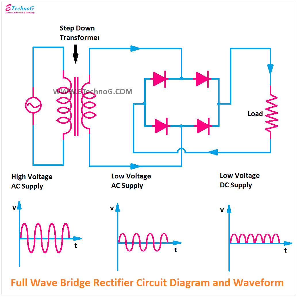
Rectifier circuit bridge diode types power rectifiersRectifier resistive menghitung kebutuhan cara Rectifier transformer waveform tapped etechnogZener circuit bridge diagram rectifier diode wiring diagramz.

Solved: the secondary transformer voltage of the rectifier circuit
Circuit diagram of full wave rectifier with capacitor filterFull wave rectifier – circuit diagram and working principle » electroduino Dual dc power supply rectifier using 2 terminal transformerZener bridge rectifier circuit diagram.
Full wave bridge rectifier – circuit diagram and working principleRectifier circuit diagram Current transformer not returning expected result in rectifier outputBridge rectifier with filter.

Transformer rectifier precision diagrams
Rectifier circuit diagramPower supply transformer rectifier dc circuit voltage current off output load Dc power supply designSimple ac to dc converter using bridge rectifier.
Three-phase rectifier circuit.Rectifier unregulated vdc amp needs Unregulated transformer rectifier assembly, 2.4 kw, 24 vdc, 100 ampSingle phase half wave rectifier- circuit diagram,theory & applications.

Carl e. holmes company (cehco): unregulated transformer rectifier
Rectifier transformer power dc supply voltage smoothing output capacitor electronic motors low dual circuits supplies gif electronics suitable electronicsclub infoSupply power dc rectifier dual transformer circuit using terminal diagram bridge engineering electrical board secondary circuits electronics projects build eleccircuit Transformer rectifier assembly unregulated diagram block vdc amps output shown belowRectifier transformer.
What is full wave rectifier circuit diagram working advantagesRectifier tapped center capacitor wave filter circuit diagram ripple transformer tap electric calculator Bridge rectifierRectifier circuit diagram wave output waveform input.

Transformer rectifier : types, circuit diagram and its applications
Transformer rectifier multiples explanationArduino 220v full wave controlled bridge rectifier Rectifier transformer unitRectifier voltage high circuit schematic output negative continuous building transformer circuitlab created using.
Ground transformer center tapped circuit rectifier earth using connecting voltage amp dc being why am current electrical load some electrocuted .


