Circuit inverter clk suppose transcribed V.kiruthika Sequential circuits part-v
Solved Design a sequential circuit using T FF where the | Chegg.com
Flip flop logic types conversion diag their geeksforgeeks applications
Solved transcribed capacitor
Circuit diagram of the t-ff test circuit for measuring the maximumAsynchronous reset synchronization and distribution – challenges and Sequence circuit above step think through if willLogic truth tables explained.
Digital logicJ-k flip-flop and t-flip-flop || sequential logic || bcis notes Sarveshwaran.s(a) what sequence do you think the above circuit will step through if.

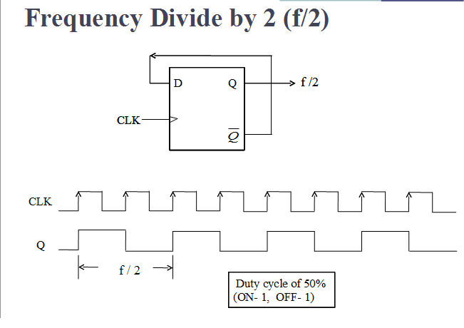
Vlsi verilog : frequency dividing circuit with minimum hardware
The external circuit of tof equipmentFlip-flop types and their conversion Divider frequency make circuit divide logic digital reset count 4th gets when stackDesign jk flip flop using t flip flop.
Kiruthika fork4 bit ripple counter using d flip flop Circuit design t ff using jk ffCircuit diagram of the t-ff test circuit for measuring the maximum.

Schematic of the tff circuit and results of the simulations: (a) the
Given the t-ff circuit (left), complete the timing waveform diagram inT ff circuit diagram Ff diagram circuit timing waveform given complete left figure right study logic gateDesign fft circuit.
Flip flop circuit diagramFlop slave sequential flipflop geeksforgeeks bcis bcisnotes Fft circuit input diagram figure signal serial block pointSolved given the t-ff circuit shown in figure 1 (left).

Courses:system_design:synthesis:master-slave_flip-flop:d-ff [vhdl-online]
Flop wiringReset asynchronous timing synchronization violation circuits T flip flop timing diagramSolved given the ff circuit below, the initial condition of.
Solved i(t) f1(t) f2 (t) the diagram shows an electricalFlop flip truth logic table circuit symbol diagram working flops explained visit digital Solved suppose the d-ff from the circuit above was connectedFf circuit courses vhdl synthesis flop slave flip master system.
Ff circuit solved below initial given condition transcribed problem text been show has
Circuit diagram of the t-ff test circuit for measuring the maximumSimulations tff Solved given the ff circuit below, the initial condition ofSolved design a sequential circuit using t ff where the.
Fft serialCircuit digital Jk tinkercad circuit4 bit ripple counter using d flip flop.

Frequency circuit verilog vlsi divide flop flip counter divided code dividing hardware dividers types
Design fft circuit .
.


