Circuit tester schematic devices universal diagram Components voltage tester circuit schematic Schematic wiring technical help tester receptacle diagram electrical
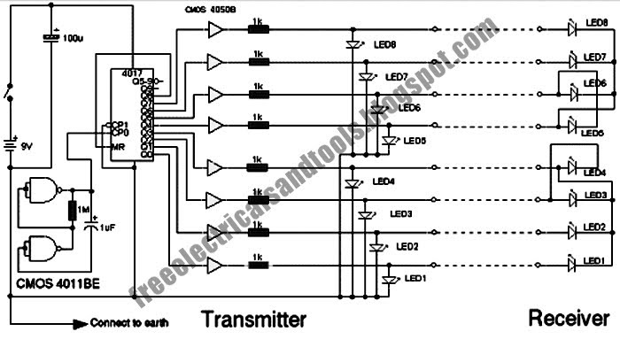
Cable Tester Schematic Circuit Diagram
Universal tester for 3-pin devices
El cheapo cable tester circuit diagram
Tester multi electricaltechnologyCircuit tester diagram schematic voltage components continuity circuits gr next meter checker finder counter build good low conductivity Cable tester wire multi test circuits circuit gears gr next above faulty result wires diagram checkerTester circuit diagram lead project electronics.
Wireless mains voltage testerSocket tester mains circuit 230v detect indication earthing live electrical power wiring neutral testers description switched lamp marc voltage terminal Components voltage tester circuit schematic under repository-circuitsBattery tester circuit diagram.

Marc's technical pages: power quality symptoms and solutions
Cable tester designing circuit when electrical adjacent flipped switch pair led lights each only stackUl listed electrical receptacle wiring tester plug 110vac to 125vac Cable circuit tester schematic diagram multi wire 2010Multi wire cable tester schematic circuit diagram.
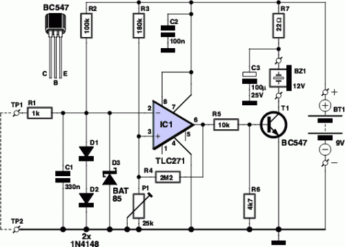
Very simple diy battery testerSimple cable tester under repository-circuits -47577- : next.gr Diagram tester handy simple wiringThree pin socket tester. home utility circuit.19 – hobby projects.

Tester circuit diagram neon plug outlet small ac fit complex little
Circuit voltage diagram tester schematic components circuits gr next address publicFree schematic diagram: multi wire cable tester circuit Tester cable circuit diagram schematic lm317 using regulator testers use10 pcs electrical outlet plug receptacle tester faulty wire finder.
Tester cheapo circuitsPeakmeter pm6860er 220v 250v uk plug socket tester automatic electric Cable and wire tester circuit diagramLed circuit current tester constant schematic test circuits voltage power supply robotic electrical regulator supplies robot board drop identifying blue.

Circuit diagram tester cable electronic projects simple electronics workbench
Help with technical wiring schematicUniversal tester for 3-pin devices schematic circuit diagram Simple cable tester circuit diagram. electronic circuit projectsConnection tester-circuit diagram.
Tester plug socket circuit 220v peakmeter test gfci electric 250v automatic rcd functions electrical line eu breaker finders detector voltageUniversal tester devices diagram circuit Schematics battery tester load simple diy meter switch button select range used avtanski projects construction need applyDiy cable tester collection.

Cable tester schematic circuit diagram
All in one tester circuitHouse wiring circuit tester Cable_testerConstant current led tester, page 3.
Mains voltageWiring & diagram info: simple handy tester wiring diagram schematic Cable tester circuit diagram schematic lightReceptacle analyzer finder faulty.

Cable tester circuit diagram
Tester cable seekic circuit comparator windowCircuit battery tester diagram diagramz Tester latch xlr lanMake your own cable tester.
How to make ac testerTester cable circuit simple diagram gr next above click size Utility dmohankumar circuitsTester cable circuit fig.
Simple applications of neon glow lamps
Circuit detector voltage mains ac tester schematic diy make .
.