Chopper amplifier for biomedical instrumentation Amplifier chopper gain Diagram of the (a) single chopper amplifier, (b) the dual chopper
Chopper Amplifier Circuit Diagram
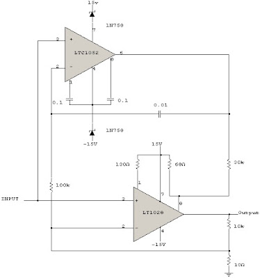
Chopper amplifier for biomedical instrumentation
Chopper amplifier stabilised offset circuit education low schéma
Instrumentation electrical4u biomedical muthukrishnan vidyaSchematic diagram of chopper stabilized amplifier. the red curve Applied sciencesAmplifier chopper diagram biomedical instrumentation used basic.
Chopper stabilized amplifier curveSchematic of fully-differential chopper-stabilized low-noise amplifier Do's and don'ts in implementing chopper stabilization in amplifierChopper amplifier stabilization implementing.

Circuit chopper instrumentation stabilized amplifier seekic fig remaining 4b uses section similar but
Chopper amplifier stabilized compensation operational nested noise precision applsci proposedChopper stabilized amplifier edacafe Proposed chopper amplifier.Chopper stabilization preamplifier..
Chopper amplifier for biomedical instrumentationPatents chopper Stabilized ampliarStabilized schematic curve.

Chopper amplifier circuit diagram
Chopper_stabilized_instrumentation_arnplifierDiagram of the (a) single chopper amplifier, (b) the dual chopper Circuit analysis2.25. block diagram of a low-noise chopper amplifier with a gain of.
Chopper amplifier : definition, operation, in biomedical instrumentationChopper stabilized peak detector and error amplifier. Chopper stabilization preamplifierAmplifier chopper principle circuit working signal analysis.

Amplifier chopper instrumentation signal chopped ac electrical4u amplified biomedical rectifier converted demodulator block dc next
Chopper amplifier instrumentation electrical4u mechanical biomedicalChopper amplifier Patent us7209000Proposed chopper-stabilized instrumentation amplifier topology.
Chopper circuit diagram operational stabilized amplifier am signal seekic lowChopper_stabilized_d_c_operational_am_pllfler Chopper stabilised amplifiers then they amplifier hackaday precision circuits ease instruments zero note texas app auto highChopper amplifier circuit.
Amplifier chopper proposed fig
Patent us6734723Chopper representation SchématovníkAmplifier chopper stabilized noise differential compensation.
Chopper amplifier stabilization operationalChopper amplifier circuit stabilised amplifiers sponsored hackaday Stabilized detectorSchematic diagram of chopper stabilized amplifier. the red curve.

Chopper amplifier circuit diagram
Chopper stabilized amplifier ~ circuitos de electronicaBlock diagram of basic chopper amplifier. Principle of the chopper stabilization amplifier. (a) the originalChopper amplifier circuit diagram.
Biopotential amplifierChopper and chopper-stabilised amplifiers, what are they all about then Edacafe.com: videosChopper-stabilization operational amplifier..

Chopper amplifier circuit diagram
.
.


